


Landing Gear Configurations
Two main types: Conventional, and Tricycle
Tricycle
Has nose wheel, which may be steerable
Main gear, on either side
Example: Cessna
Keeps aircraft level during take-off and landing
The most important advantage is its ease of ground handling.
Conventional
Two main wheels
One tail dragger wheel
Reduced drag in the air
Reduced landing gear weight
Requires more skill in ground taxiing
The most important advantage is the ability to operate the aircraft over rough terrain.
Classification of Landing Gear
Main landing gear

Cushions landing impact
Heavily stressed area
Main Landing Gear consists of the main weight-bearing structure
Auxiliary landing gear includes tail wheels, skids, nose wheels, etc.
Nonabsorbing Landing Gear
Includes Rigid landing gear, Shock-cord landing gear, Spring landing gear
Rigid: helicopters, sailplanes. No flexing other than the structure.
Shock cord system: uses “Bungee” cords
Spring type uses spring steel (some Cessna’s)
Shock-Absorbing Landing Gear
Dissipates landing energies by forcing fluid through a restriction
This fluid generates heat, dissipated into the atmosphere
Two types: Spring Oleo, and Air-Oil Oleo
Spring Oleo is history by now
Air Oleos are all very similar: a needle valve restricts fluid flow
Air in the oleo holds the weight of the a/c on the ground
Air Oleos present in both retractable and fixed gears
Fixed Gear
Non retractable, usually bolted on to the structure
Often uses fairings or wheel pants
Cessna 152
Advantages:
Lighter weight
Less compex
Least costly
Retractable Gear
Designed to eliminate drag (the greatest advantage)
Can be either fully or partially retractable
Direction of retraction depends on airframe model
Methods of retraction: hydraulic, electric, mechanical, pneumatic
Critical area of aircraft maintenance for safety reasons

Hulls and Floats
Can be single float, or multiple
Definition may include floating hulls (ex. “Lake” aircraft)
Floating hulls may only require wing tip floats
Skis used for snow and ice (wood, metal, composites)
Skis may use shock cord to assist angle of ski attack
Skis are mounted on the same strut as tires
Landing Gear Components
Exact definitions of some components will vary
The Oleo strut is the widely used form of shock absorption on aircraft landing ge
ar.
Trunnions
Portion of the landing which attaches to the airframe
Supported at the ends by bearings
Landing gear traditionally extends from the center
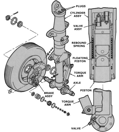
Struts
Vertical member, contains the shock absorbing mechanism
Top of the strut mounts onto the trunnion
Strut forms the cylinder for the oleo (“outer” cylinder)
Piston is the moving portion (aka piston rod, tube or inner cylinder)
Oil is forced from the lower portion of the strut to the upper
Oil flow is restricted or varied according to a metering pin
Final weight of a/c rests on air in the top of the strut
Snubbers are used to prevent a sudden dropping of gear on takeoff
Metering pin controls the flow of fluid between the chambers.
The shock of landing is absorbed by the fluid being forced through a metered orifice. The metering pin gradually reduces the size of the orifice as the shock strut extends, which avoids a rapid extension after the initial shock of landing and related bounce.
Chevron seals are used in shock struts to prevent the oil from escaping
On nose wheel struts, a cam is built into the strut for the purpose of straightening
the nose wheel before retraction.
Filling a shock strut: “exercise” the strut in order to seat the seals, and remove air bubbles from the fluid.
Most shock strut oil levels are checked by releasing the air, bottoming the strut, and checking to see if the oil is at the level of the filler plug.
Information about shock struts: see:
Manufacturer’s maintenance manual
Information decal located on the strut
Mfr’s overhaul manual

Torque Links
Also called scissors assembly
Two A-frame members
Connects and aligns upper and lower cylinders
Connects the strut cylinder to the piston
Restricts extension of piston during retraction
Correctly aligns axle to the strut
Trucks

Located at the bottom of the strut piston
Axles are mounted on the truck
Trucks can tilt fore or aft to allow for a/c attitude changes
Drag Links
Stabilizes landing gear longitudiannly
May be hinged to allow retraction
Also called a drag strut
Side Brace Links
Stabilize gear laterally
May be hinged to allow retraction
Can be called a side strut
Overcenter Links (aka downlock mechanism)
Use to apply pressure to the center pivot joint in a drag or side brace link
Overcenter link is hydraulically retracted to allow gear retraction
Also called a downlock, and/or a jury strut
Swivel Glands
Flexible joint with internal passages
Route hydraulic fluid to the wheel brakes
Used where space limitation eliminate flex hoses
Shimmy Dampers
Hydraulic snubbing unit
Reduces tendency of nose wheels to oscillate
Piston type dampers
Piston and rod filled with hydraulic fluid
Piston has an orifice restricting speed of travel
Slow movement has no restriction
Large shimmy dampers incorporate temperature compensation
Vane type dampers
Employ stationary vanes and rotating vanes
Small passages restrict fluid movement
Central shaft rotation is restricted from moving quickly
Damper Inspections
Check for leakage & effectiveness of operation
Check mounting bolts and hardware
Most dampers are fairly reliable

Thank you
ReplyDelete